| 401-37 |
Install and Test PCI bus 8 channels relay output photo isolator input adapter on RedHat
1. Install Device Driver
This sample is under REDHAT 8.0 KERNEL 2.4.18-14.
You can do it in the ' text-mode ' or use the Terminal of System tools in ' graphic-mode '.
1.1 Download Device Driver
Download driver you need from as follows
dpciindust_2.4.18.tgz for KERNEL 2.4.18 Release Date:2003/3/05
Download the driver to /tmp
You can use 'uname -a' command to check your kernel's version.

1.2 Install step
To install device driver , perform the following steps.
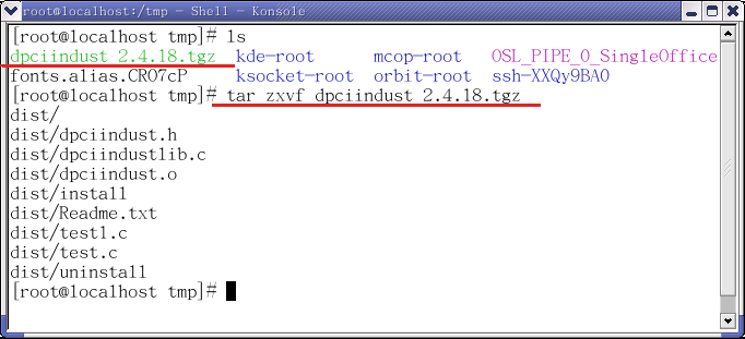
Step 1: Extract the file
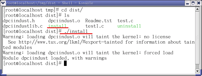
Step 2: Execute the install file to install
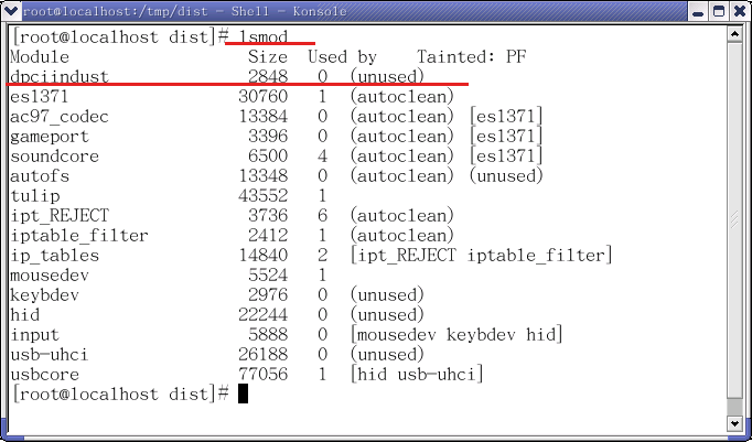
Step 3: Please use "lsmod" command to check
Step 4: Please edit /etc/rc.local to add a command line as follows:

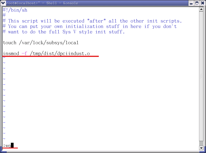
Step 5: Please reboot systems.
Step 6: Please use 'lsmod' to check after system restarted. You can find the PCI Industrial Control card.
If you don't find the device, please check ' /etc/rc.local ' file.
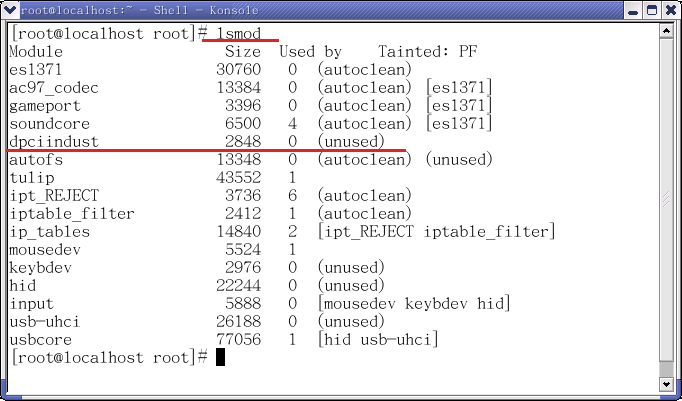
2.Uninstall the driver
If you want to remove the driver.You can use 'ls' command to find 'uninstall' file.Then execute the file.

3. Self test the card:
3.1 The test tool
You can use 8 Photo /8 Relay board , 16 photo board or 16 relay board to test.
Please connect it to port1 of PCI INDUSTRAL CARD.
3.2 The test programs
3.2.1 Connect the 8 Photo /8 Relay Board
The device driver already includes three test programs about 8 Photo /8
Relay Board .
1.8photo_8relay_test.c: It auto tests Relay Output ON/OFF of Decision
Industial card.
2.8photo_8relay_test1.c: Tests Relay Output and Photo Input.
3.8photo_8relay_test2.c: Manuly tests Output.
Step 1:
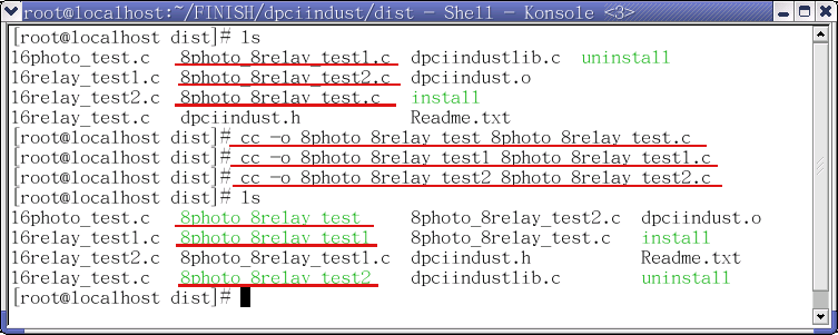
Please compile the '8photo_8relay_test.c' '8photo_8relay_test1.c'
'8photo_8relay_test2' files as following step:
Then it will create the '8photo_8relay_test' '8photo_8relay_test1'
'8photo_8relay_test2' file.
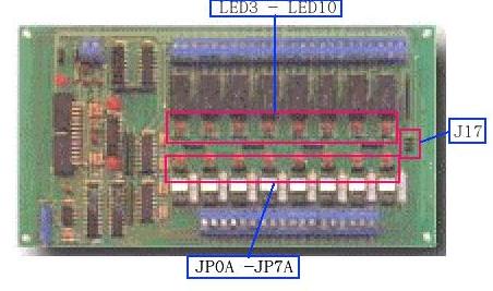
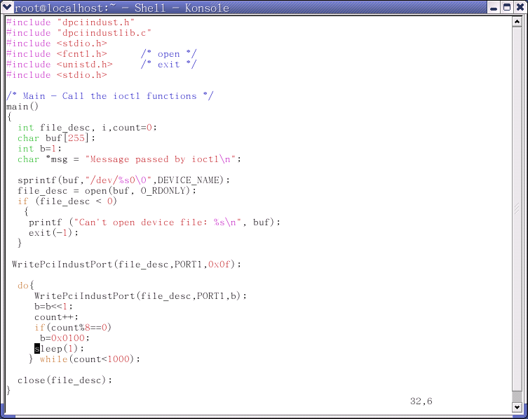
Step 2: Please execute the '8photo_8relay_test' file to test Relay output. You will see LED light from
LED3 to LED10 Auto ON and OFF on the 8 Photo /8 Relay board .

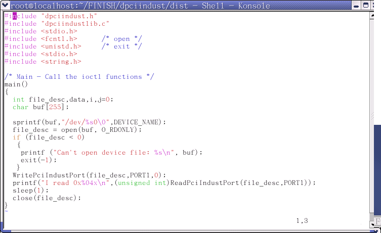
The 8photo_8relay_test.c's content is as follows:
Step 3: Please execute '8photo_8relay_test1' to test Relay and Photo.
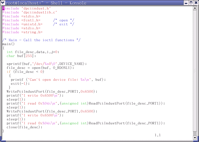
You must short JP17-2 ,then shout one or more of JP0A ~ JP7A on 8 Photo /8 Relay board .
You can see number in ' I read .....' line and LED3, LED5, LED8, LED9 lights are turned on.
By default, you can see ' I read 0xffff '.The LED11 ~ LED18 is on.
If you short all of JP0A ~ JP7A on the board. You can see ' I read 0xff00'. The LED11~LED18 is off.

The 8photo_8relay_test1.c's content is as follows:
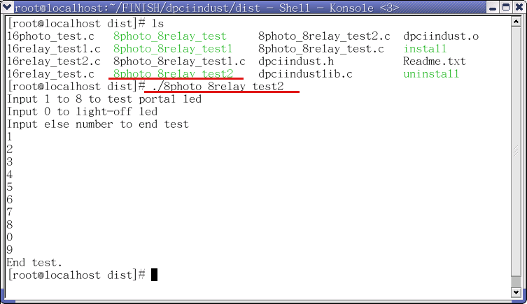
Step 4: Please execute '8photo_8relay_test2' to manuly test Relay .
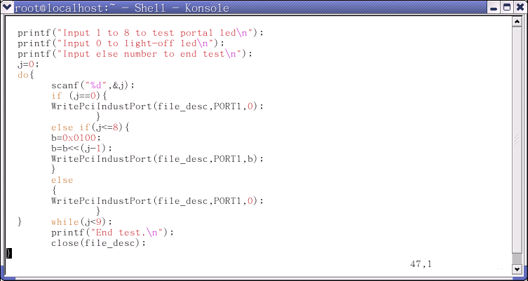
You can input 1 ~ 8 to test PORTA1 LED.
Input 1, the LED3 is turned on. Input 2, the LED4 is turned on.
Input 3, the LED5 is turned on. Input 4, the LED6 is turned on.
Input 5, the LED7 is turned on. Input 6, the LED8 is turned on.
Input 7, the LED9 is turned on. Input 8, the LED10 is turned on.
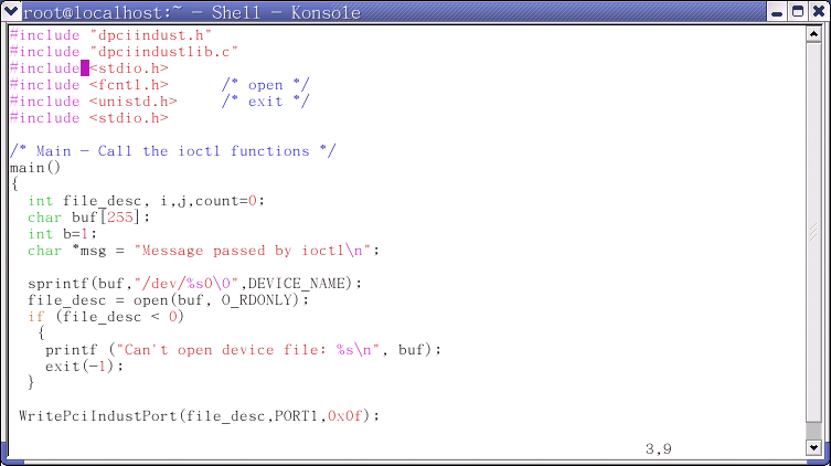
The 8photo_8relay_test2.c's content is as follows:
3.2.2 Connect the 16 Relay Board
The
device driver already includes three programs about 16 Relay Board .
1.16relay_test.c: It auto tests Relay Output ON/OFF of Decision
Industial card.
2.16relay_test1.c: Tests Relay Output and Photo Input.
3.16relay_test2.c: Manuly tests Output.
Step 1:
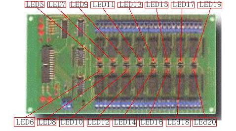
Please compile the '16relay_test.c' '16relay_test1.c' '16relay_test2'
files as following step:
Then it will create the '16relay_test' '16relay_test1' '16relay_test2'
file.
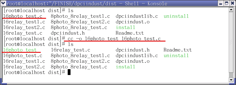
Step 2: Please execute the '16relay_test' file to test Relay output. You will see LED light from LED5 to LED20 Auto ON and OFF on the 16 Relay board .

The 16relay_test.c's content is as follows:
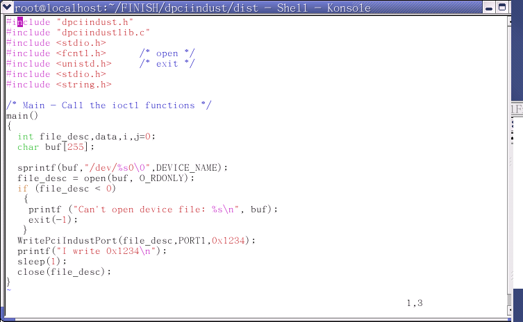
Step 3: Please execute '16relay_test1' to test Relay . You can see number in ' I read 0x1234' line and led13(1),
led7(2), led14 led16(3),led10(4) lights are on.

The 16relay_test1.c's content is as follows:
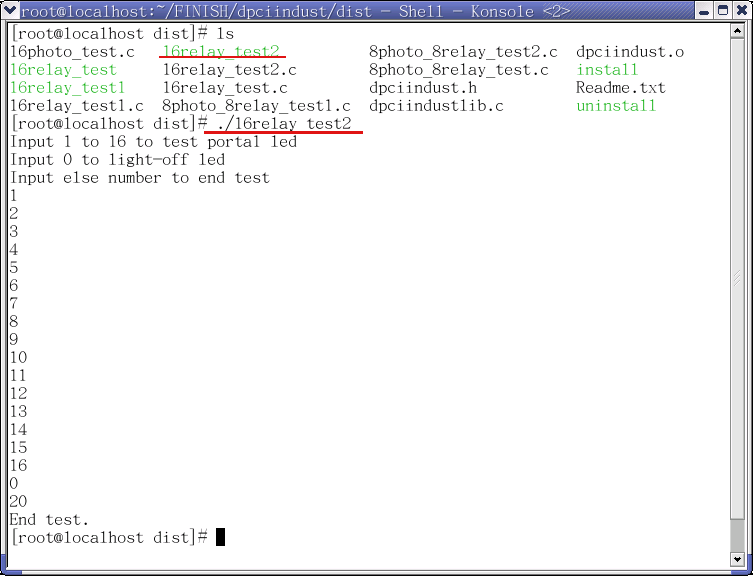
Step 4: Please execute '16relay_test2' to manuly test Relay .
You can input 1 ~ 16 to test relay output.
Input 1, the LED6 is turned on. Input 2, the LED8 is turned on.
Input 3, the LED10 is turned on. Input 4, the LED10 is turned on.
The rest can be down in the same way.
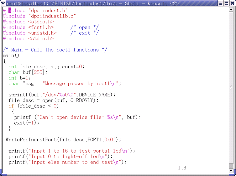
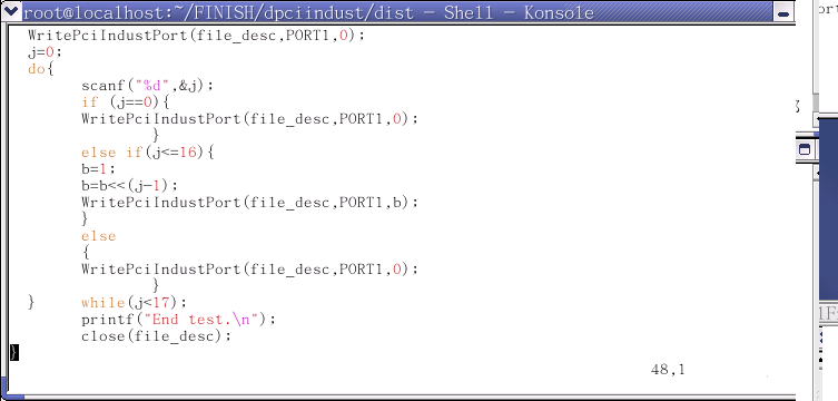
The 16relay_test2.c's content is as follows:
3.2.3 Connect the 16 Photo Board
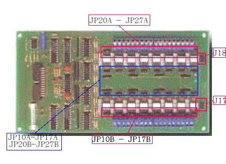
Step 1: Please compile the '16photo_test.c' ' files as following step:

Step 2: Please execute the '16photo_test' file to test Relay output. You can short J17-2 and J18-2.
And short 2-3 in JP10B - JP17B and JP20A to JP27A.
Then you can short one or more of JP10A – JP17A and JP20B -JP27B.
You can see number in 'I read .....' line.

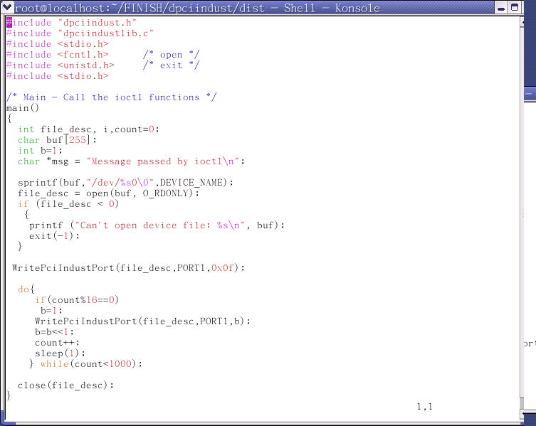
The 16photo_test.c's content is as follows:
