
PCI bus 8 channels relay / output photo isloator input adapter
Product Code: 8PCIPHOTO/RELAY
The PCI bus 8 channels relay output / photo isolator input adapter is a 32 bits PCI bus board with Plug and Play (PnP) features, it is a programmable I/O interface card for PC/486, Pentium, or compatibles. The PnP features let hardware configuration for IRQ and I/O address is detected by BIOS automatically, you don't need set switch and jumper.
The PCI bus 8 channels relay output / photo isolator input adapter provides relay output functions and photo isolator input functions. The relay output part provides 8 relays to drive 8 different output channels. Each relay channel can be used to control ON / OFF of external devices, to drive external high power relays, to activate alarms ... etc. The photo isolator input part provides 8 photo couple digital input channels, which allow the input signals to be completely floated and prevent the ground loop.
Please refer Decision Industrial Interface (DII) Software manual to know how to install device driver for PCI bus 8 Port Channels Relay Output/ Photo Isolator Input adapter, and how to write application program by using Active-X Components.
The
features of the PCI bus 8 channels relay output / 8 photo isolator
input adapter are:
| 1. | 32 bits PCI bus with Plug and Play (PnP) features. |
| 2. | Support 8 relay output channels and 8 photo couple input channels. |
| 3. | Max contact rating for relay: 120V AC/DC 1AMP. |
| 4. | Attraction time for relay: 3 ms. |
| 5. | Fall off time for relay: 2 ms. |
| 6. | Isolation resistance for relay: 100M OHM. |
| 7. | Life expectancy for relay: 100 million operations at signal level load. |
| 8. | Allow the photo input signals to be completely floated and prevent the ground loops. |
| 9. | There are two kinds of boards were be selected : 002 board provides external/internal power input and 004 board provides only external power input. |
| 10. | Activation voltage for 002 board: Input range
from 0 to 20V
0 to 1.5V inactive 3 to 20V active |
The
package includes following item
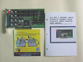
Check that your PCI bus 8 channels relay output/photo isolator input package includes the following items:
1.
PCI bus 8 channels relay output/photo isolator input board.
2. Demo Program.
3. User manual.
4. Warranty form.
 |
HARDWARE INSTALLATION
Your PCI bus 8 channels relay output/photo isolator input adapter is designed to be inserted in any available PCI slot in your PC/486, Pentium or compatibles. In order to gain access to the expansion slots, follow the steps listed below:
| 1. | Turn off all power to your computer and all peripheral devices before installing your 8 channels relay output/photo isolator input adapter. |
| 2. | Remove the cover of the computer. |
| 3. | Insert the 8 channels relay output/photo isolator input adapter into any available PCI slot. Make sure the adapter is firmly seated in the chosen slot. |
| 4. | Replace the cover of the computer. |
| 5. | Turn on the power of your computer, the PnP features will recognize the 8 channels relay output/photoisolator input adapter. |
HARDWARE CONFIGURATION
Before you use the 8 channels relay output/ photo couple input adapter, you must ensure that the I/O address. Observe the figure in the follows, the proper jumper settings for the 8 channels relay output/photo couple input adapter is described in the following.
1. I/O Address
The PnP feature will get base I/O address automatically, where
Base Address + 0:
Relay output
channel 1 to
| 7 | 6 | 5 | 4 | 3 | 2 | 1 | 0 |
| RL8 | RL7 | RL6 | RL5 | RL4 | RL3 | RL2 | RL1 |
Photo isolator input channel 1 to 8.
|
7
|
6
|
5
|
4
|
3
|
2
|
1
|
0
|
|
IN8
|
IN7
|
IN6
|
IN5
|
IN4
|
IN3
|
IN2
|
IN1
|

| Jumper | Description |
| Open | Select opto+ and opto- Voltage Signal Input |
| Short | 12V Internal Input |
| Pin |
Description
|
|
1
|
Relay channel 1, NO
|
|
2
|
Relay channel 1, COM
|
|
3
|
Relay channel 1, NC
|
|
4
|
Relay channel 2, NO
|
|
5
|
Relay channel 2, COM
|
|
6
|
Relay channel 2, NC
|
|
7
|
Relay channel 3, NO
|
|
8
|
Relay channel 3, COM
|
|
9
|
Relay channel 3, NC
|
|
10
|
Relay channel 8, NO
|
|
11
|
Relay channel 8, COM
|
|
12
|
Opto channel 1, +
|
|
13
|
Opto channel 2, +
|
|
14
|
Opto channel 3, +
|
|
15
|
Opto channel 4, +
|
|
16
|
Opto channel 5, +
|
|
17
|
Opto channel 6, +
|
|
18
|
Opto channel 7, +
|
|
19
|
Opto channel 8, +
|
|
20
|
Relay channel 4, NO
|
|
21
|
Relay channel 4, COM
|
|
22
|
Relay channel 4, NC
|
|
23
|
Relay channel 5, NO
|
|
24
|
Relay channel 5, COM
|
|
25
|
Relay channel 6, NO
|
|
26
|
Relay channel 6, COM
|
|
27
|
Relay channel 7, NO
|
|
28
|
Relay channel 7, COM
|
|
29
|
GND
|
|
30
|
Opto channel 1, -
|
|
31
|
Opto channel 2, -
|
|
32
|
Opto channel 3, -
|
|
33
|
Opto channel 4, -
|
|
34
|
Opto channel 5, -
|
|
35
|
Opto channel 6, -
|
|
36
|
Opto channel 7, -
|
|
37
|
Opto channel 8, -
|
Isolated input: The digital signal input with isolated protection.
Photo Isolator :
Word File 4N35
Hyper Link
PDF File TLP620
Relay :
Word File BT-12S
Hyper Link
Catalog |
|
| |
Manual |
| |
Device Driver |
| |
Self Test Software
& Sample Code |
| |
Web Based DAQ |
| |
Application |
| |
Q&A |