
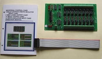
The 16 Channel Relay Output board
provides 16 Single Pole Double Throw (SPDT) relays to drive 16 digital
output lines. Each of relay channel can be used to control ON/OFF of
external devices, to drive external high power relays, to activate
alarms…etc. there are 16 LED indicators correspond to 16 relays, when
relay is energized, the corresponding LED is light. The +12V power
source is user selectable from internal PC bus or external power
supplier.
The features of 16 Channel Relay Output
Board are:
| 1. |
Support 16 SPDT relay
channels. |
| 2. |
LED indicates when relay is energized. |
| 3. |
Internal and external power selectable. |
| 4. |
Built in screw terminals for easy wiring. |
| 5. |
The Normal Open (NO), Normal Close (NC), and Common contacts (COM) of each relay are brought out to the screw connector. |
| 6. |
Max contract
rating: 150V/DC 2amp, 125V/AC 2 amp. |
| 7. |
Breakdown voltage:AC/DC
500V minimum/ |
| 8. |
Relay on time: 3 ms
typical. |
| 9. |
Relay off time: 2 ms
typical. |
| 10. |
Total switching time: 10
ms typical. |
| 11. |
Isolation resistance: 100
M OHM minimal. |
| 12. |
Life expectancy: 5 million
operation at full load. |
| 13. |
Screw terminal: accept #22 to #12 awg wire. |
| 14. |
Power consumptio |
| +12V: 40mA for each relay,
total 0.55 amp for all relays are energized. +5V : < 0.2 amp. -12V: < 0.1 amp. |
|
| |
The package includes following item The package contains: 1.16 Channel Relay Output board 2.One 26 pins flat cable. 3.User's manual. |
|
|

1. Signal assignment of 26 pins flat cable
|
Pin
|
Description
|
Pin
|
Description
|
|
No. |
|
No.
|
|
|
1
|
+12V
|
14
|
I/O line 9
|
|
2
|
GND
|
15
|
I/O line 10
|
|
3
|
+12V
|
16
|
I/O line 11
|
|
4
|
GND
|
17
|
I/O line 12
|
|
5
|
I/O line 0
|
18
|
I/O line 13
|
|
6
|
I/O line 1
|
19
|
I/O line 14
|
|
7
|
I/O line 2
|
20
|
I/O line 15
|
|
8
|
I/O line 3
|
21
|
/CS1
|
|
9
|
I/O line 4
|
22
|
/CS2
|
|
10
|
I/O line 5
|
23
|
+5V
|
|
11
|
I/O line 6
|
24
|
GND
|
|
12
|
I/O line 7
|
25
|
-12V
|
|
13
|
I/O line 8
|
26
|
GND
|
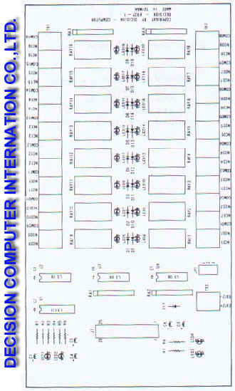
The normal open, normal close, and common contacts signal of each relay are shown in the follows.
|
Pin
|
Description
|
Description
|
|
1
|
NC01
|
NC09
|
|
2
|
NO01
|
NO09
|
|
3
|
COM01
|
COM09
|
|
4
|
NC02
|
NC010
|
|
5
|
NO02
|
NO010
|
|
6
|
COM02
|
COM010
|
|
7
|
NC03
|
NC011
|
|
8
|
NO03
|
NO011
|
|
9
|
COM03
|
COM011
|
|
10
|
NC04
|
NC012
|
|
11
|
NO04
|
NO012
|
|
12
|
COM04
|
COM012
|
|
13
|
NC05
|
NC013
|
|
14
|
NO05
|
NO013
|
|
15
|
COM05
|
COM013
|
|
16
|
NC06
|
NC014
|
|
17
|
NO06
|
NO014
|
|
18
|
COM06
|
COM014
|
|
19
|
NC07
|
NC015
|
|
20
|
NO07
|
NO015
|
|
21
|
COM07
|
COM015
|
|
22
|
NC08
|
NC016
|
|
23
|
NO08
|
NO016
|
|
24
|
COM08
|
COM016
|
 |
|
||||||||||||||||||
2.4 LED messages Other information LEDs are as follows
LED1 If you are ready to send data to the relays 0~7, LED1 will be light. Otherwise that will be LOW (0) and LED1 be off. LED2 If you are ready to send data to the relays 8~15, LED2 will be light. Otherwise that will be LOW (0) and LED2 be off. LED3 The LED3 is an indicator to show the power is supplied normally. LED4 LED4 indicates the JP1 status.
| |||||||||||||||||||
Catalog |
|
| |
Manual |
| |
Device Driver
|
| |
Self Test Software
& Sample Code |
| |
Web Based DAQ
|
| |
Application
|
| |
Q&A |