
8 Channel SSR / logical output board
Product Code: A8SSR
The 8 Channel SSR / logical
output board provides 8 SSR output channels and 8 logical output
channels. The SSR can be treated as a relay. Each SSR channel can be
used to control ON/OFF of external devices, to drive external high
power devices to activate alarms. Etc. There are 8 LED indicators
correspond to 8 SSR channels, when SSR is energized, the corresponding
LED is light.
The output voltages of logical output channel are user selectable; user may select +5V, 12V, or the external voltage lower than 40V DC. There are 8 LED indicator corresponds to 8 logical output channels, when output voltage is low, then the corresponding LED is light.
The output voltages of logical output channel are user selectable; user may select +5V, 12V, or the external voltage lower than 40V DC. There are 8 LED indicator corresponds to 8 logical output channels, when output voltage is low, then the corresponding LED is light.
The features of 8 Channel SSR/Logical output board are:
| 1. |
Support 8 SSR output channels and
8 logical output channel. |
| 2. |
The SSR operation characteristics are similar to relay. |
| 3. |
Provides more than 12 types of SSR output module, which are tabled below. |
| 4. |
LED indicates when signal is energized. |
| 5. |
Built in screw terminals for easy wiring. |
| 6. | Maximum voltage of logical output channel is 40V DC. |
| 7. |
Maximum sink current of logical
output channel is 100mA. |
| 8. |
Screw terminal: accept #22 to #12
awg wire. |
| 9. |
The specifications of SSR are: |
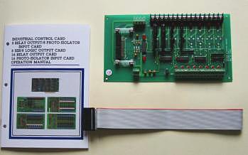
Check that your PCI bus Industry Control Card package includes the following items:
The package contains:
1.8 Channel SSR/ Logical Output board.
2.One 26 pins flat cable.
3.User's manual.
 |
| |
|
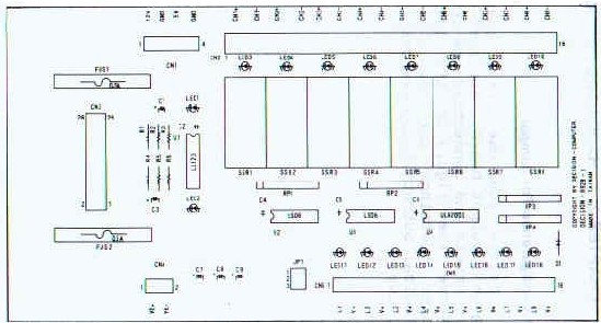
2.1 Configuration For Jumper
Before you use the 8 Channel SSR/ Logical Output board, you must ensure that the jumpers and connectors are set correctly. Observe the figure in the following, the proper settings for the 8 Channel SSR / Logical Output boards are described in the follows.
Before you use the 8 Channel SSR/ Logical Output board, you must ensure that the jumpers and connectors are set correctly. Observe the figure in the following, the proper settings for the 8 Channel SSR / Logical Output boards are described in the follows.
| 1. |
Internal / external
power selection. |
 |
|
| JP1
is used to select output voltage, when JP1-1 is short, then the output
voltage is 5V. When the Jp1-2 is short, we select 12V as the output
voltage. Suppose the output voltage we required is not 5V or 12V, the
JP1-3 is short, to use the VEXT voltage. TB3 is used to connect external power; the configuration is shown in the follows. The maximum input voltage is 40V DC. |
|
2.3 Signal Assignments
1. Signal assignment of 26 pins flat cable
The 26 pins flat cable connector is connected to digital output interface card such as: industry control, TTL I/O, 8255 I/O, connector is shown in the following.
| Pin |
Description
|
Pin |
Description
|
|
1
|
+12V
|
14
|
I/O line 9
|
|
2
|
GND
|
15
|
I/O line 10
|
|
3
|
+12V
|
16
|
I/O line 11
|
|
4
|
GND
|
17
|
I/O line 12
|
|
5
|
I/O line 0
|
18
|
I/O line 13
|
|
6
|
I/O line 1
|
19
|
I/O line 14
|
|
7
|
I/O line 2
|
20
|
I/O line 15
|
|
8
|
I/O line 3
|
21
|
/CS1
|
|
9
|
I/O line 4
|
22
|
/CS2
|
|
10
|
I/O line 5
|
23
|
+5V
|
|
11
|
I/O line 6
|
24
|
GND
|
|
12
|
I/O line 7
|
25
|
-12V
|
|
13
|
I/O line 8
|
26
|
GND
|
The SSR output signals and logical output signals are shown in the follows. TB1 is the screw connector of SSR output channel and TB2 is the screw connector of logical output channel.
|
No.
|
TB1
|
TB2 |
|
1
|
CH0+
|
CH8
|
|
2
|
CH0-
|
V+
|
|
3
|
CH1+
|
CH9
|
|
4
|
CH1-
|
V+
|
|
5
|
CH2+
|
CH10
|
|
6
|
CH2-
|
V+
|
|
7
|
CH3+
|
CH11
|
|
8
|
CH3-
|
V+
|
|
9
|
CH4+
|
CH12
|
|
10
|
CH4-
|
V+
|
|
11
|
CH5+
|
CH13
|
|
12
|
CH5-
|
V+
|
|
13
|
CH6+
|
CH14
|
|
14
|
CH6-
|
V+
|
|
15
|
CH7+
|
CH15
|
|
16
|
CH7-
|
V+
|
| Catalog |
|
| |
Manual  |
| |
Device Driver
|
| |
Self Test Software
& Sample Code |
| |
Web Based DAQ
|
| |
Application
|
| Q&A |