
8 channel relay output Isolator input board
Product Code: A8RELAY/8PHOTO
The 8 channel relay output / isolator input board provides
relay output function and isolator input function. The relay output
part provides 8 Single Pole Double Throw (SPDT) relays to drive 8
digital output lines. Each relay channel can be used to control ON/OFF
of external devices, to drive external high power relays, to activate
alarms etc. There are 8 LED indicators correspond to 8 relays, when
relay is energized, the corresponding LED is light. The +12V power
source is user selectable from internal PC bus or external power
supplier.
The isolator input part provides 8 Photo isolated Digital Input Channel, which allow the input signals to be completely floated and prevent the ground loop. There are 8 LED indicators corresponds to 8 input channels, when the input channel is activated at high stat, the corresponding LED is light. The power source is user selectable from internal PC bus or external power supplier.
The isolator input part provides 8 Photo isolated Digital Input Channel, which allow the input signals to be completely floated and prevent the ground loop. There are 8 LED indicators corresponds to 8 input channels, when the input channel is activated at high stat, the corresponding LED is light. The power source is user selectable from internal PC bus or external power supplier.
| a. |
Support 8 SPDT relay channels. |
| b. |
LED indicates when relay is
energized. |
| c. |
Internal and external power selectable. |
| d. |
Built in screw terminals for easy writing. |
| e. |
The Normal Open (NO), Normal Close (NC), and Common contacts (COM) of each relay are brought out to the screw connector. |
| f. | Max contact rating: 150V/DC 2amp, 125V/AC 2amp. |
| g. |
Breakdown voltage: AC/DC 500V
minimum. |
| h. |
Relay on time: 3 ms typical. |
| i. |
Relay off time: 2 ms typical. |
| j. |
Isolation resistance: 100 ms
typical. |
| k. |
Life expectancy: 5 million
operation at full load. |
| l. |
Screw terminal: accept #22 to #12
awg wire. |
| m. |
Power consumption: |
| n. |
+12V: 40mA for each relay, total
0.55 amp for all relays are energized. +5V : < 0.2 amp. -12V : < 0.1 amp. |
| a. |
Support 8 opto-isolated input
channels. |
| b. |
LED indicated when input channel
is activated. |
| c. |
Internal and external power
selectable. |
| d. |
Built in screw terminals for easy
wiring. |
| e. |
Allow the input signals to be
completely floated and prevent the ground loops. |
| f. |
Isolated or non-isolated modes
selectable. |
| g. |
Input signals are buffered with
voltage comparators. |
| h. |
Input threshold voltage adjustable. |
| i. |
Breakdown voltage: 1500 VDC. |
| j. |
Screw terminal: accept #22 to #
12 awg wire. |
| k. |
Input current: 80mA maximum for
each isolated input. |
| l. |
Input voltage: 30VDC maximum for
each isolated input. |
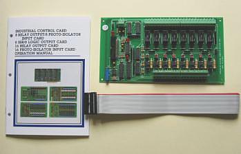
1.8 Channel Relay Output / Isolator Input Board.
2.One 26 pins flat cable.
3.User's manual.
 |
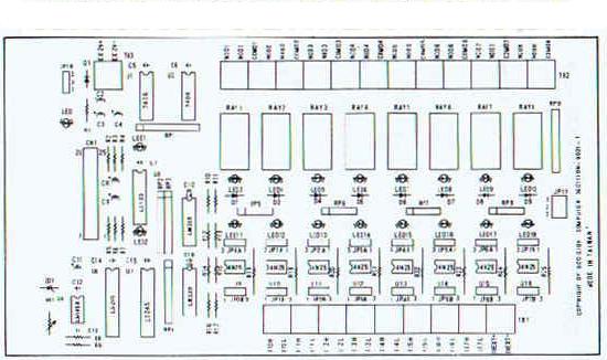
Setting the threshold voltage of Photo Isolator, adjust VR which is on the PCB to get the desired threshold voltage. The external input voltage which is over the threshold voltage will be recognized as HIGH (1) and the relative led will be light. Otherwise that will be LOW (0) and led be off.
2.2 Relay Output Function
1.Internal / external power selection.

JP-18 is to select external
or PC bus power supply JP18-1, JP18-2 short mean PC bus power
JP18-2, JP18-3 short mean external power. Suppose you connect more
than two 8 channel relay output/isolator input boards, we suggest you
use external power.
2.External power supplier
TB3 is used to connect +12V external power, the configuration is shown in the follows.
2.External power supplier
TB3 is used to connect +12V external power, the configuration is shown in the follows.
The input voltage is 12V
(+/-) 1V, and the power consumption for all 8 channel relay output is
0.3 amp. Â
2.3 Isolator Input Function
1.Internal/External power selection

2.3 Isolator Input Function
1.Internal/External power selection
User may use jumpers to
select external or internal power supply. When the input signal is
non-power signal (eg. Switch
etc��), internal power is
selected, the PC bus power +12V or 5V can be selected by user. When
the input is voltage or current, the external supplier is mean the
signal itself that can adjusted from +5V to +30V.
JP17 is used to select internal or external power supply of input channels. When JP17-1 is shorted, the PC bus +12V power is selected, when JP17-2 is shorted, the PC bus +5V power is selected. If we short JP17-3, then the external power supplier is selected.
2.External Power Supplier in the follows.
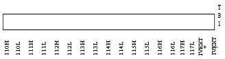
The power supplier of I10
to I17 are TB1 and the external power range is from 5V to 30V.
3.Isolated and Non-Isolated
3.Isolated and Non-Isolated
JP0B to JP7B are used to
select isolated or non-isolated. When JPXB-1, JPXB-2 is sort, then the
corresponds channel is in isolator mode. When JPXB-2, JPXB-3 is short, the IxL is short with system GND. So the external signal is in non-isolated mode. JP0A to JP7A are used to select power signal input or non-power signal input for the correspond channel. JpxA-1 and JpxA-2 short is power signal input mode. JpxA-2, JpxA-3 short is non-power input mode.
2.4 Signal Assignment
1.Signal assignment of 26 pins flat cable.
 The 26 pins flat cable connector is connected to digital input / output interface card such as: industry control, TTL/I/O, 8255 I/O signal assignment of this connector is shown in the following.
2.Signal assignment of screw connector
The normal open, normal close, and common contracts signal of each relay are shown in the follows.
corresponds channel is in isolator mode. When JPXB-2, JPXB-3 is short, the IxL is short with system GND. So the external signal is in non-isolated mode. JP0A to JP7A are used to select power signal input or non-power signal input for the correspond channel. JpxA-1 and JpxA-2 short is power signal input mode. JpxA-2, JpxA-3 short is non-power input mode.
2.4 Signal Assignment
1.Signal assignment of 26 pins flat cable.
 The 26 pins flat cable connector is connected to digital input / output interface card such as: industry control, TTL/I/O, 8255 I/O signal assignment of this connector is shown in the following.
|
Pin
|
Description
|
Pin
|
Description
|
|
1
|
+12V
|
14
|
INPUT 01
|
|
2
|
GND
|
15
|
INPUT 02
|
|
3
|
+12V
|
16
|
INPUT 03
|
|
4
|
GND
|
17
|
INPUT 04
|
|
5
|
OUTPUT 00
|
18
|
INPUT 05
|
|
6
|
OUTPUT 01
|
19
|
INPUT 06
|
|
7
|
OUTPUT 02
|
20
|
INPUT 07
|
|
8
|
OUTPUT 03
|
21
|
/CS1
|
|
9
|
OUTPUT 04
|
22
|
/CS2
|
|
10
|
OUTPUT 05
|
23
|
+12V
|
|
11
|
OUTPUT 06
|
24
|
GND
|
|
12
|
OUTPUT 07
|
25
|
-12V
|
|
13
|
INPUT 00
|
26
|
GND
|
2.Signal assignment of screw connector
The normal open, normal close, and common contracts signal of each relay are shown in the follows.
| No. |
TB2
|
|
1
|
NC01
|
|
2
|
NO01
|
|
3
|
C1
|
|
4
|
NC02
|
|
5
|
NO02
|
|
6
|
COM02
|
|
7
|
NC03
|
|
8
|
NO03
|
|
9
|
COM03
|
|
10
|
NC04
|
|
11
|
NO04
|
|
12
|
COM04
|
|
13
|
NC05
|
|
14
|
NO05
|
|
15
|
COM05
|