|
USER'S
MANUAL INDUSTRIAL CONTROL CARDS (ISA)
|
8 channel industry control adapter
Product Code: A8 IND
|
INTRODUCTION
The 8-channel
industry control board is a programmable I/O interface for PC/XT,
PC/AT, PC/386, or compatibles. It provides total 8 i/O digital I/O
ports, each I/O port contains 8 I/O lines, and can be set either input
or output by the user's program. The signal assignments of 8-channel
industry control board is designed as a standard configurations, so
that it can be used to connect to the expansion card family are
16/8-channel relay output board, 16/8-channel isolator input board,
8-channel SSR/Logic output board etc.
|
The features of 8-channel
industry control board are:
|
1.
|
Provides 8 I/O
ports.
|
2.
|
Each I/O port contains 8 digital I/O lines, total
64 I/O lines.
|
3.
|
Port address selectable.
|
4.
|
Standard signal
assignment to connect to expansion board family. |
|
The package includes following
item
|
The package contains:
1.
|
8-channel industry control
board.
|
2.
|
Four expansion flat
cable with 26 pins connector.
|
3.
|
User's manual.
|
4.
|
Diskette.
|
|
HARDWARE INSTALLATION
|
Your 8-channel industry control
board is designed to inserted in any available slot in your computer.
In
order to gain access to the expansion slots and the program switches on
the main board, follow the steps listed in the followings:
|
1.
|
Set the 8-channel industry
control board switch.
|
2.
|
Turn off all power of
your computer and all peripheral devices before installing your
8-channel industry control board.
|
3.
|
Remove the cover of
the computer.
|
4.
|
Insert you reconfigured
board into any available slot. Make sure your I/O card is firmly seated
in the chosen slot.
|
5.
|
Replace the cover of
the computer.
|
6.
|
You are now ready to
use your 8-channel industry control board for several applications.
|
HARDWARE
CONFIGURATION
|
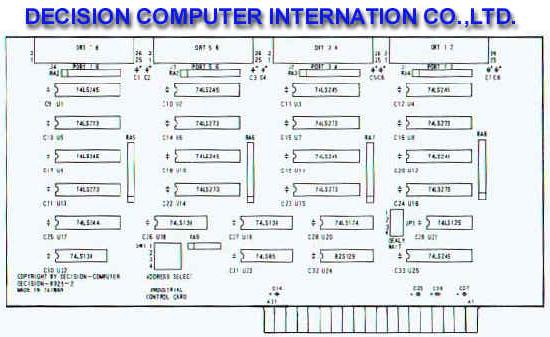
Before you use the
8-channel industry control board, you must ensure that the I/O address
is set correctly. Observe the figure in the follows; the proper
settings for the 8-channel industry control board are described in
the following.
|
|
|
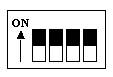
1. I/O Address
Dip switch is used to set I/O address,
the I/O address mapping are
|
|
|
|
| SW1 |
SW2
|
SW3 |
SW4 |
I/O ADDRESS
|
ON
|
ON
|
ON
|
ON
|
180H V 187H
|
ON
|
ON
|
ON
|
OFF
|
188H V 18FH
|
ON
|
ON
|
OFF
|
ON
|
190H V 197H
|
ON
|
ON
|
OFF
|
OFF
|
198H V 19FH
|
ON
|
OFF
|
ON
|
ON
|
1A0H V 1A7H
|
ON
|
OFF
|
ON
|
OFF
|
1A8H V 1AFH
|
ON
|
OFF
|
OFF
|
ON
|
1B0H V 1B7H
|
ON
|
OFF
|
OFF
|
OFF
|
1B8H V 1BFH
|
OFF
|
ON
|
ON
|
ON
|
1C0H V 1C7H
|
OFF
|
ON
|
ON
|
OFF
|
1C8H V 1CFH
|
OFF
|
ON
|
OFF
|
ON
|
1D0H V 1D7H
|
OFF
|
ON
|
OFF
|
OFF
|
1D8H V 1DFH
|
OFF
|
OFF
|
ON
|
ON
|
1E0H V 1E7H
|
OFF
|
OFF
|
ON
|
OFF
|
1E8H V 1EFH
|
OFF
|
OFF
|
OFF
|
ON
|
1F0H V 1F7H
|
OFF
|
OFF
|
OFF
|
OFF
|
1F8H V 1FFH
|
|
|
|
2.
Pin Assignments
|
|
|
|
1.Connector 1 (J1)
|
|
2. Connector 2
(J2)
|
|
Pin
|
Description
|
Pin
|
Description
|
|
1
|
+12V
|
14
|
port1/line1
|
|
2
|
GND
|
15
|
port1/line2
|
|
2
|
+12V
|
16
|
port1/line3
|
|
3
|
GND
|
17
|
port1/line4
|
|
4
|
port0/line0
|
18
|
port1/line5
|
|
5
|
port0/line1
|
19
|
port1/line6
|
|
6
|
port0/line2
|
20
|
port1/line7
|
|
7
|
port0/line3
|
21
|
/CS1
|
|
8
|
port0/line4
|
22
|
/CS2
|
|
9
|
port0/line5
|
23
|
+5V
|
|
10
|
port0/line6
|
24
|
GND
|
|
11
|
port0/line7
|
25
|
12V
|
|
12
|
port1/line0
|
26
|
GND
|
|
|
|
Pin
|
Description
|
Pin
|
Description
|
|
1
|
+12V
|
14
|
port3/line1
|
|
2
|
GND
|
15
|
port3/line2
|
|
3
|
+12V
|
16
|
port3/line3
|
|
4
|
GND
|
17
|
port3/line4
|
|
5
|
port2/line0
|
18
|
port3/line5
|
|
6
|
port2/line1
|
19
|
port3/line6
|
|
7
|
port2/line2
|
20
|
port3/line7
|
|
8
|
port2/line3
|
21
|
/CS3
|
|
9
|
port2/line4
|
22
|
/CS4
|
|
10
|
port2/line5
|
23
|
+5V
|
|
11
|
port2/line6
|
24
|
GND
|
|
12
|
port2/line7
|
25
|
12V
|
|
13
|
port3/line0
|
26
|
GND
|
|
3. Connector 3 (J3)
|
|
4. Connector 4
(J4)
|
|
Pin
|
Description
|
Pin
|
Description
|
|
1
|
+12V
|
14
|
port1/line1
|
|
2
|
GND
|
15
|
port1/line2
|
|
2
|
+12V
|
16
|
port1/line3
|
|
3
|
GND
|
17
|
port1/line4
|
|
4
|
port0/line0
|
18
|
port1/line5
|
|
5
|
port0/line1
|
19
|
port1/line6
|
|
6
|
port0/line2
|
20
|
port1/line7
|
|
7
|
port0/line3
|
21
|
/CS1
|
|
8
|
port0/line4
|
22
|
/CS2
|
|
9
|
port0/line5
|
23
|
+5V
|
|
10
|
port0/line6
|
24
|
GND
|
|
11
|
port0/line7
|
25
|
12V
|
|
12
|
port1/line0
|
26
|
GND
|
|
|
|
Pin
|
Description
|
Pin
|
Description
|
|
1
|
+12V
|
14
|
port7/line1
|
|
2
|
GND
|
15
|
port7/line2
|
|
3
|
+12V
|
16
|
port7/line3
|
|
4
|
GND
|
17
|
port7/line4
|
|
5
|
port2/line0
|
18
|
port7/line5
|
|
6
|
port2/line1
|
19
|
port7/line6
|
|
7
|
port2/line2
|
20
|
port7/line7
|
|
8
|
port2/line3
|
21
|
/CS7
|
|
9
|
port2/line4
|
22
|
/CS8
|
|
10
|
port2/line5
|
23
|
+5V
|
|
11
|
port2/line6
|
24
|
GND
|
|
12
|
port2/line7
|
25
|
12V
|
|
13
|
port3/line0
|
26
|
GND
|
|
DIAGNOSTIC
|
|
The
CONTROL.BAS program provides diagnostic routine to test your industry
control board under MS/DOS operating system. Moreover, you can connect
expansion board such as 16 channel photo isolate input board, 16
channel
relay output board, 8-channel relay output/ 8-channel photo isolate
input board, and 8-channel SSR output / 8-channel logical output board
to check / 8-channel logical output board to check whether these boards
are good.
NOTE: In order to prevent violation of input data
from input port, please reset the input port before perform input
procedure, this mean you must output 255 to input port to reset it.
BASIC EXAMPLE:
OUTPUT: OUT &H180,VALUE
INPUT : OUT &H180,255: DATA=INP(&H180)
|
|
|
|
|
|