Digital Input
Many types of digital signals
like switch closures, relay contacts, and TTL laver compatible can be
read by digital I/O card directly. Some type of digital signals input
may require signal conditioning like reduce higher-level voltage to TTL
level. A variety of signal conditioning module is available to provide
isolation and device circuitry protection functions.
Switches
Switches are pretty straightforward to wire. For security reason switch
contacts are always drawn in the OFF position when in systems
initialize. In the case of rotary switches the wiper arm will always be
connected to the first contact, which will be the off position.
|
|
Operating Voltage
|
10 30 V DC
|
|
Hysteresis
|
Less than 10 %
|
|
Max. Switch Rate
|
1.5 KHz ( M12/M18 ) ; 2K
Hz ( S17/S18 ) ; 500 Hz ( PB )
|
|
Power-On Reset Time
|
20 ms
|
|
Circuit Protection
|
(a) output short circuit
& (b) reverse polarity of supply voltage
|
|
Max. Load cirrent
|
100 mA
|
|
Sealing
|
Conforming to IP67
|
|
Cable Length
|
2 meter, oil retardent,
grey color
|
|
Writing Diagram
|
Brown, black and blue as
standard
|
|
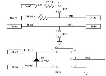
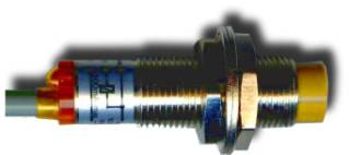 Proximity switch
|
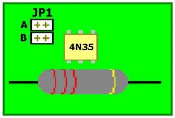
Jumper
|
Description
|
|
Open
|
Select opto+ and opto-
Voltage Signal Input
|
|
Short
|
Select Open/Close from
Relay Output Contract Point
|
a. JP XA JP
XA ( open )
b. JP XB JP XB ( open )
The JP1A and JP1B are
used to select voltage signal of photo input channel 1, and the JP2A and
JP2B are used to select voltage signal of photo input cannel 2, …etc.
When we open both jumpers, it means we use opto+ and opto- signals as
input voltage, in this mode, the hardware will isolate input signal and
power. Otherwise, when the jumpers are short, it means we need not
input voltage from opto+ and opto-; in this mode, when opto+ and opto-
are shorted, the input signal is 1, when opto+ and opto- are open, the
input signal is 0; Under this mode, it only isolate input signal.
If you only use PCI bus 4 channels relay output / photo isolator input
adapter, these jumpers are used to select input signal. Otherwise, if
you connect terminal board to this adapter, please open all jumpers that
on the adapter, because you need select input signal from terminal
board. |
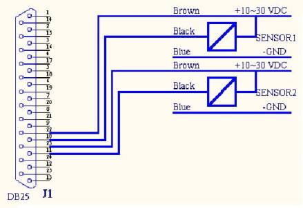
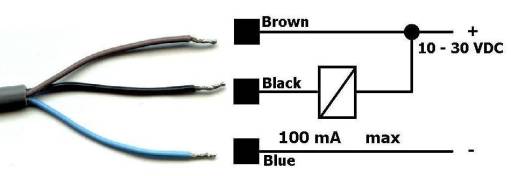
2. Sensors Line
a. Brown Connect to +12V
( Vcc ) & Opoto channel 1 +(PCI 4 Photo / 4 Relay Card)
b. Black Connect to
Opoto channel 1- (PCI 4
Photo / 4 Relay Card)
c. Blue Connect to Ground ( Gnd )
3.Test Line
4. Circuit
5. DB25 Connector Ping Assignment
|
Pin
|
Description
|
|
1
|
Ground
|
|
2
|
Relay channel 1, COM
|
|
3
|
12V
|
|
4
|
Relay channel 2, COM
|
|
5
|
12V
|
|
6
|
Relay channel 3, COM
|
|
7
|
Ground
|
|
8
|
Relay channel 4, COM
|
|
9
|
12V
|
|
10
|
Opto channel 1, -
|
|
11
|
Opto channel 2, -
|
|
12
|
Opto channel 3, -
|
|
13
|
Opto channel 4, -
|
|
14
|
Relay channel 1, NC
|
|
15
|
Relay channel 1, NO
|
|
16
|
Relay channel 2, NC
|
|
17
|
Relay channel 2, NO
|
|
18
|
Relay channel 3, NC
|
|
19
|
Relay channel 3, NO
|
|
20
|
Relay channel 4, NC
|
|
21
|
Relay channel 4, NO
|
|
22
|
Opto channel 1, +
|
|
23
|
Opto channel 2, +
|
|
24
|
Opto channel 3, +
|
|
25
|
Opto channel 4, +
|
|
|