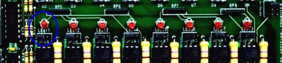
Digital Input
Many types of digital signals
like switch closures, relay contacts, and TTL laver compatible can be
read by digital I/O card directly. Some type of digital signals input
may require signal conditioning like reduce higher-level voltage to TTL
level. A variety of signal conditioning module is available to provide
isolation and device circuitry protection functions.
 |
 |
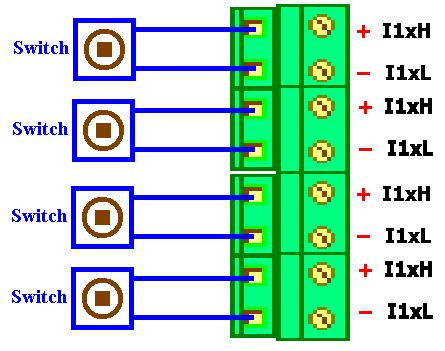
Switches
Switches are pretty
straightforward to wire. For security reason switch contacts are always
drawn in the OFF position when in systems initialize. In the case of
rotary switches the wiper arm will always be connected to the first
contact, which will be the off position.
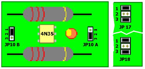
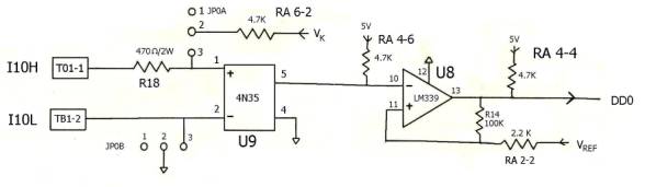
Photo Isolator :
Word File 4N35
Hyper Link
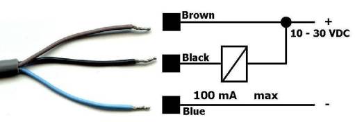
*Signal Input without Power
| SENSOR To 16 Photo
Isolator Board |
||||||||||||||||||||||
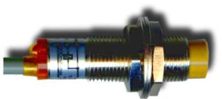
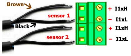
| Application
Example Proximity switch [
General Specifications ]
|
Catalog |
|
| |
Manual
|
| |
Device Driver |
| |
Self Test
Software & Sample Code |
| |
Web
Based DAQ |
| |
Application
|
 |
Q & A |